Impedance matching is a fundamental concept in electrical engineering that plays a crucial role in optimizing signal transfer between circuit components, circuits and devices. When two components or systems have different impedance levels, a mismatch occurs, resulting in power reflections, signal loss, and reduced efficiency. Impedance matching techniques aim to minimize these reflections and maximize power transfer, ensuring optimal performance and signal integrity. Impedance matching is required in circuits like matching impedance between AM modulator and RF mixer, impedance matching between antenna and RF pre-amplifier circuit in AM receiver circuit as well as any wireless RF circuits like FM transmitter.
One widely used technique for impedance matching is the L-matching network, which employs inductors and capacitors to adjust impedance levels. This network is particularly effective when the source and load impedances are complex and cannot be easily matched using other methods. The L-matching network is known for its simplicity, versatility, and wide applicability across various frequency ranges.
The L-matching network consists of two reactive elements: an inductor (L) and a capacitor (C). The components are connected in a specific configuration to achieve the desired impedance transformation. The network can be connected in series or parallel, depending on the specific requirements of the circuit.
To understand the operation of an L-matching network, let's consider a scenario where a source impedance, represented by Zs, needs to be matched to a load impedance, represented by Zl. The goal is to find suitable values for the inductor (L) and capacitor (C) that will transform Zs to Zl, thus achieving impedance matching.
The L-matching network operates by providing reactance that cancels out the undesired reactance from either the source or load impedance, effectively balancing the impedance levels. By adjusting the values of L and C, the network can cancel both the real (resistive) and imaginary (reactive) parts of the impedance.
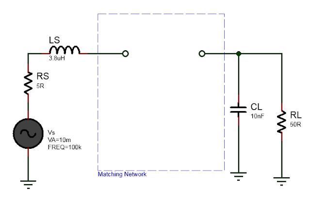
Here we will consider matching source impedance \(Z_S\) and load impedance \(Z_L\). The source impedance has real resistance of \(R_S=5\Omega\) and parasitic inductance \(L=138.731nH\). The load impedance has real resistance of \(R_L=50\Omega\) and parasitic capacitor \(C=454.910pF\).
That is, \(Z_S=R_S + j X_S\) is the source impedance and \(Z_L=R_L + j X_L\) is the source impedance, where,
\(X_L = ωL\) (inductive reactance)
\(X_C = \frac{1}{wC}\) (capacitive reactance)
Here, ω represents the angular frequency of the signal. The values of L and C can be determined by equating the reactances to the desired values that achieve impedance matching. By solving these equations, the appropriate component values can be calculated.
Example of Impedance Matching with L matching network.
The circuit diagram to match source and load is shown below.
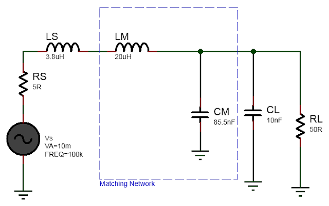
It was shown in Real Impedance matching with L matching network that to match Rs=5Ohm source to RL=50Ohm we can use L matching network in low pass configuration and at frequency 100KHz the series inductor is 23.8uH and the parallel capacitor is 95.5nF. Since we already have a series parasitic inductance of 2uH so the actual value of inductance L in the L-matching network is L=23.8uH-3.8uH=20uH. Similarly since we already have the parasitic load capacitance of 10nF and we need 95.5nF in the L matching network the actual capacitance value of the matching network is C=95.5nF-10nF=85.5nF.
The completed impedance match circuit using L matching network is shown below.
 So the idea here is to first find the L and C values assuming there is no parasitic source and load reactances and solve for real impedance matching between source and load. Then absorb the additional inductance and capacitances required into the L matching network component values.
The frequency response graph of the above matched circuit is shown below.
It's important to note that L-matching networks are frequency-dependent, and the values of L and C must be selected based on the specific operating frequency or frequency range of the system. For wideband applications, multiple L-matching networks may be required to cover different frequency bands.In conclusion, impedance matching is a critical aspect of electrical engineering, ensuring efficient signal transfer between devices. The L-matching network offers a straightforward and effective method for impedance transformation, allowing for improved power transfer and reduced signal reflections. By carefully selecting the values of inductors and capacitors, engineers can achieve optimal impedance matching in a wide range of applications, resulting in enhanced performance and signal integrity.
Read more:
[1] Homogeneous and Inhomogeneous transmission line
[2]


