When the source and load impedance are unequal then there will be power losses in the transmission line. In order to avoid power loss impedance matching circuit are used. Thus impedance matching is the process of using a circuit so that maximum power transfer occurs between unequal source and load resistor. This is important for example in matching the impedance of an RF antenna to the front end RF amplifier, between RF amplifier and RF mixer or AM modulator in AM transmitter and AM radio receiver and/or FM modulator or FM demodulator circuits.
One of the popular and simple impedance matching technique is L matching network method. A combination of capacitor(C) and inductor(L) are inserted between the source and load impedances and the LC inserted looks like shape "L" and so the matching network is called L impedance matching network.
The source and load impedance can have reactance part or be only real. Here it is shown how to use the L matching network for impedance matching when the source and the load impedance are real(that is, they are purely resistive and does not contain reactances). There are two cases, either the source resistor is greater than load resistor or vice versa. The following is the method of using L matching network for matching network for these two cases.
Impedance matching when \(R_0 < R_L\)
Let the source resistor be \(R_0 = 5 \Omega\) and load resistor be \(R_L = 50 \Omega\) so that \(R_0 < R_L\). A matching network can be used between these two unmatched resistors so that maximum power transfer from source to load happens. This is illustrated below.
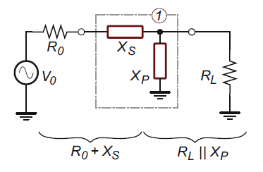
We can insert L-matching network as shown below.
The L-matching network consist of two reactances, a series reactance Xs and a parallel reactances Xp. These two reactances are chosen such that the total series reactance \(R_0+Xs\) is equal to the total parallel reactance \(R_L||X_p\). The effect of adding the reactances is that the series reactance is increased and the parallel reactance is decreased. If the series reactance \(X_s\) is an inductor and the parallel reactance \(X_p\) is a capacitor then the L-matching circuit is a low pass topology. Similarly if the series reactance \(X_s\) is a capacitor and the parallel reactance \(X_p\) is a inductor then the L-matching circuit is a high pass topology.
At the frequency of interest, the series impedance and the parallel impedance must be complex conjugate of each other. This means that at the frequency of interest, the Q-factor, Qs of the series reactances and the Qp of the parallel reactances must be equal.
We have,
\(Q_s=\frac{X_s}{R_0}\) ----->(1)
and \(Q_p=\frac{R_L}{X_p}\) ----->(2)
It can be proved that,
\(R_p \approx Q^2 R_s\) ----->(3)
when, \(X_p \approx X_s\) ------>(4)
Assuming,
\(Q \approx Q_p \approx Q_s\) then, \(Q = \sqrt{\frac{R_L}{R_0}-1}\) ------>(5)
for the circuit above we have,
\(Q = \sqrt{\frac{50\Omega}{5\Omega}-1}=3\)
Using Q=3 in equation (1) and (2) to calculate the series and parallel reactances we get,
\(X_s= Q R_0 = 3 \times 5\Omega=15\Omega\)
and, \(X_p= \frac{R_L}{Q_p} = \frac{50\Omega}{3}=16.66\Omega\)
If \(X_s=15\Omega\) and we use low pass configuration, that is Xs is inductive reactance then, if the design frequency 100KHz, we have,
\(L=\frac{X_s}{2 \pi f} = \frac{15 \Omega}{2 \times 3.14 \times 100KHz} = 23.8 \mu H\)
and, \(C=\frac{1}{2 \pi \times f \times X_p} = \frac{1}{2 \times \pi \times 100KHz \times 16.66\Omega} = 95.5 nF \)
The designed circuit is shown below along with the frequency response of the circuit.
Impedance matching when \(R_0 > R_L\)
Now consider that the source resistor RL=50Ohm is greater than the load resistor RL=5Ohm.
We can insert L matching impedance circuit such that the source resistors see 50Ohm when looking into the matching network. Similarly, the load resistor should see 5Ohm when looking into the matching network.
In this case, a series reactance Xs is added to the load resistor to increase the combined resistance and a parallel reactance Xp is added in parallel to the source resistor so that the combined resistance is decreased. This L section impedance network is shown below.
If serial reactance Xs is an inductor and the parallel reactance Xp is a capacitor than the L matching network is low pass topology.
At the design frequency the serial impedance and the parallel impedance must be complex conjugate to each other for maximum power transform. When this happens the impedance matches the source and the load impedances, and the Q of each section are equal.
\(Q_s = \frac{X_s}{R_L}\) ------>(6)
\(Q_p = \frac{R_0}{X_p}\) ------>(7)
The Q factor is given by (5) above as,
\(Q \approx Q_p \approx Q_s\) then, \(Q = \sqrt{\frac{R_0}{R_L}-1}\)
For \(R_0=5\Omega\) and \(R_L = 50 \Omega\)
\(Q = \sqrt{\frac{50}{5}-1}=3\)
Using (6) we have,
\(X_s = Q_s R_0 = 3 \times 5\Omega =15\Omega\)
If Xs is capacitor then,
\(X_s = \frac{1}{2\pi f C}\)
or, \(C = \frac{1}{2\pi f X_s} = \frac{1}{2\pi (100KHz) (15\Omega)} =0.1\mu F\)
Using (7) we have,
\(X_p = \frac{R_L}{Q_p} = \frac{5\Omega}{15} =0.33\Omega\)
If Xp is inductor then,
\(X_p = 2\pi f L\)
or, \(L = \frac{X_p}{2\pi f} = \frac{0.333\Omega}{2\pi (100KHz)} =525.47nH\)
The completed circuit diagram and the frequency response graph of the designed L impedance network are shown below.
The benefits of using L-matching networks extend beyond impedance
matching. They can also help improve power efficiency, reduce signal
reflections, and minimize standing waves. Additionally, L-matching
networks can be used in various applications, such as RF circuits,
antennas, amplifiers, and transmission lines.
However, it's worth
mentioning that L-matching networks have their limitations. They may
introduce additional losses due to the resistive components of the
inductor and capacitor. These losses can affect overall system
performance, especially at higher frequencies. Additionally, the
L-matching network may have a limited range of impedance transformation,
making it unsuitable for certain extreme impedance ratios.


