Scilab is a free, open-source software for numerical computation, data analysis, and simulation, similar to MATLAB. It includes powerful tools like Xcos for system modeling. When paired with Arduino, Scilab becomes a powerful platform for learning and experimenting with real-time data acquisition and control systems. Using the Arduino Toolbox for Scilab, users can connect Scilab running on PC to an Arduino board via serial communication, enabling real-time data monitoring, signal processing, and control algorithm testing directly from Scilab. For example, you can read sensor data from an Arduino, process it in Scilab to filter noise, and then send control signals back to actuators like motors or LEDs—making it perfect for applications like live temperature control, robotics, and automatic lighting systems. Xcos is a graphical editor for modeling and simulating dynamic systems—part of the open-source software Scilab (similar to MATLAB). This tutorial shows you how to control an LED using Scilab/Xcos and an Arduino board. You'll build a simple simulation model in Xcos that sends signals to the Arduino to blink an LED in real time.
In order for the co-simulation between Arduino and Scilab/Xcos to work,we need to configure both on the Arduino side and the Scilab/Xcos side. Basically for arduino we upload a sketch so that the Arduino can handle and communicate with the Scilab/Xcos. On the Scilab/Xcos, we need to add Arduino simulation parts as ATOM module for inter communication between Arduino board and Scilab. We will start with Arduino part, then configure Scilab part.
🧰 Requirements
🖥️ Software
-
Scilab (version ≥ 5.4)
-
Arduino Toolbox for Scilab: Install from ATOMS
🔌 Hardware
-
Arduino board (e.g., Uno, Mega, Nano)
-
1 LED
-
220Ω resistor
-
Breadboard & jumper wires (optional)
🔧 Step 1: Upload Arduino Interface Sketch
-
Download and open the file
toolbox_arduino_v5.inoin the Arduino IDE.To compile this file, you will also need the following c++ and header files:
Once you have downloaded these files, you can add them as Zip library install directly from the Arduino IDE.
-
Connect your Arduino via USB.
-
Select the correct COM port and board under the "Tools" menu.
-
Upload the sketch to the board.
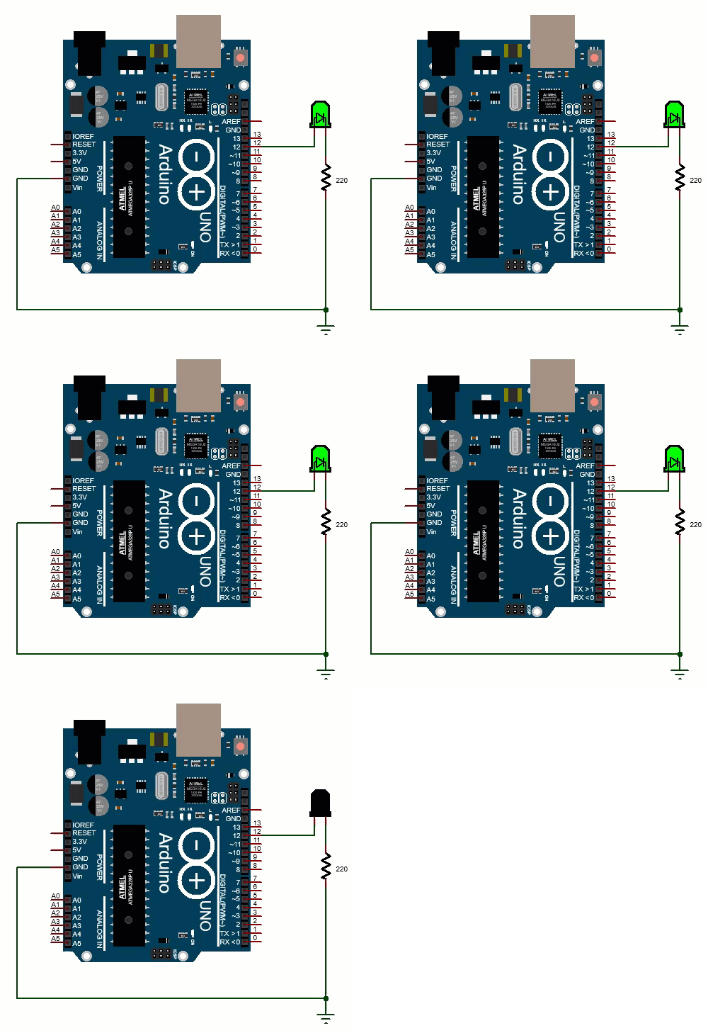
⚙️ Step 2: Set Up the Circuit
-
Connect the LED:
-
Long leg (anode) → Pin 12 (digital pin)
-
Short leg (cathode) → resistor → GND
-
-
Confirm LED is wired properly.
🛠 Step 3: Create the Xcos Model
🧩 Required Blocks:
-
Arduino Setup: Configure port (e.g.,
COM3) and sampling period. -
Pulse Generator (PULSE_SC): Create blinking signal.
-
Arduino Digital Write: Output signal to pin 12.
-
Scope (from Arduino toolbox): Visualize the LED signal.
🔌 Model Wiring:
The setting for the Arduino setup block is shown below. In this case, the com port is 3, yours maybe different.
Time-sample block setting
The settings for the time sampling block is shown below.
Pulse Generator Settings
-
Amplitude: 1
-
Period: 1 (seconds)
-
Pulse Width: 50 (%)
-
Phase Delay: 0
This creates a 1 Hz square wave (1 sec ON, 1 sec OFF).
On the physical hardware side, connect a LED to pin 12 of Arduino as shown in the figure below.
▶️ Step 4: Run the Simulation
-
Press the play button in Xcos.
-
The LED should blink every second.
-
The scope will show the digital signal toggling between 0 and 1.
Watch the following video to learn how to blink an LED by interfacing Scilab/Xcos directly with Arduino via serial communication for real-time data acquisition and control.
📊 Tips for Real-Time Use
-
Ensure sampling time in the Arduino Setup block is small (e.g.,
0.1seconds). -
Use Nyquist rule: sampling time < half of the pulse period


