Bandpass filters are crucial in allowing a certain range of frequencies to pass through while attenuating frequencies outside that range. Bandpass filter circuits find extensive usage across diverse applications. Within
the realm of telecommunications, bandpass filters specifically cater to
the audio frequency spectrum (20 Hz to 20 kHz), serving purposes in
modems and speech processing. Below is visual representations that showcase a typical bandpass filter responses.
Types of Band Pass Filter circuit
There are various types of band pass filter circuit, each with its own configuration and characteristics.
Here are a few common types:
Passive Bandpass Filter
Comprised of passive components such as resistors, capacitors, and
inductors. It allows a specific range of frequencies to pass through
without needing an external power source. Passive filters can be first order, 2nd order and higher order depending upon the how many first order bandpass filter is being used. Although passive filters can be used in audio frequency range it is unique in that for high frequencies RF circuits passive filters are the only possible solution unlike active filters which can only be used in the audio to midband frequencies.
Active Bandpass Filter
The active bandpass filter utilizes active components like operational amplifiers along with resistors and capacitors to create a bandpass response. Any circuit topology that uses operational amplifier or active elements such as transistor or diode are known as active bandpass filter. Examples of active bandpass filter are multiple feedback bandpass filter, sallen-key bandpass filter, twin-t bandpass filter, state variable band pass filter. For designing active filter see How to Design Active Band Pass Filter.
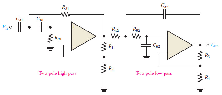
An example of creating active bandpass filter is to use LPF and HPF designed with two op-amps and then cascading them to create active bandpass filter.
Multiple Feedback Bandpass Filter
The multiple feedback bandpass filter uses an operational amplifier with multiple feedback paths, offering flexibility in adjusting bandwidth and center frequency. The following shows multiple feedback band pass filter circuit diagram.
Here we have used a single operational amplifier to design the active bandpass filter. Operational amplifier like LM741, LM358, LM324, TL072 etc can be used to design this filter for audio frequency range.
Sallen-Key Bandpass Filter
A type of active filter topology that is popular is the Sallen-Key filter configuration. Sallen-Key filters employ operational amplifiers and capacitors to create a bandpass filter response. It's simple and commonly used due to its ease of design. You can use the online Sallen-Key LPF Calculator for designing Sallen-Key filter.
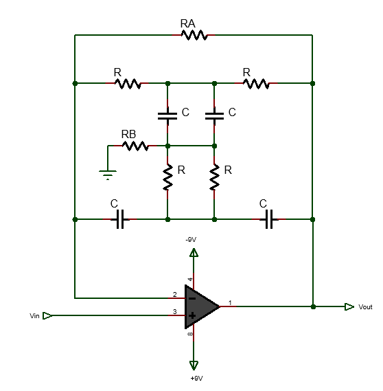
Twin-T Bandpass Filter
The Twin-T is another popular filter topology. It utilizes two T-shaped RC networks to form a bandpass response. Such low pass and high pass T-shaped RC can be used for designing both passive Twin-T bandpass filter and active Twin-T bandpass filter.
State Variable Bandpass Filter
State Variable bandpass filter uses multiple op-amps and capacitors to provide multiple outputs with different filter characteristics. It allows for adjustable center frequency, bandwidth, and gain.
These filters differ in complexity, ease of design, frequency response characteristics, and components used. The choice of filter type depends on factors like required bandwidth, center frequency, the order of the filter, and the application's specific needs.


